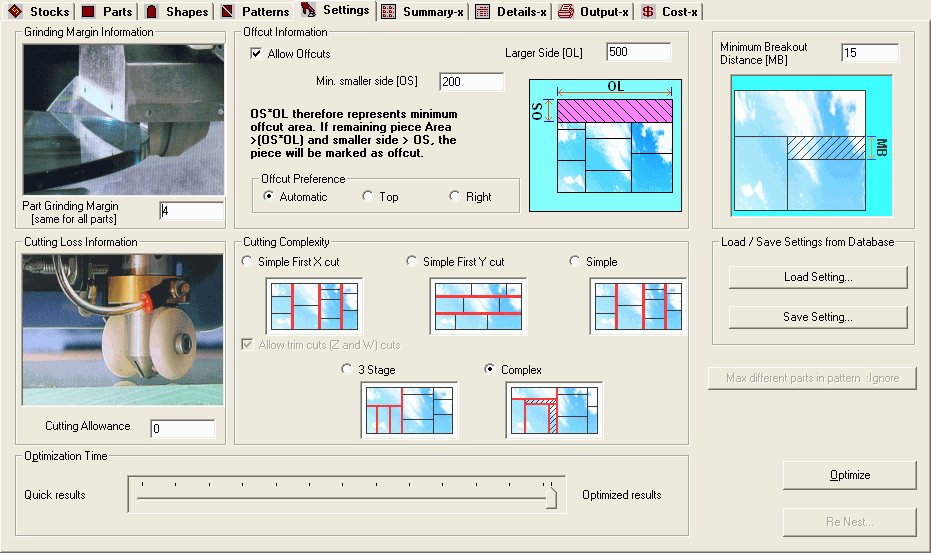
Settings page have following sections
a) Grinding Margin: After Cutting the parts from stocks, you want to polish the sides of the parts then some allowance has to be given for the parts. This is included in the grinding margin. This grinding margin is same for all parts.
b) Offcut Information: A piece of waste of the stock sheet that can be considered as re-usable is called Offcut. For a piece to be considered as a offcut, its smaller dimension should be larger than the "Min. Smaller Side" value, and area should be greater than the value (Min. Smaller Side * Larger Side). By specifying the "Larger side" you specify the minimum area of the offcut.
Consider the following examples... with the following settings...
Min Smaller Side : 100 Larger Side: 500
Hence any piece will be considered an offcut only if it has an area > 100 * 500 = 50000, and the smaller side is > 100.
| Smaller Side | Larger side | Area | Is Offcut |
| 50 | 1200 | 60000 | No : The smaller side is lesser than the smaller side. |
| 125 | 450 | 56250 | Yes |
| 125 | 300 | 37500 | No : the area is lesser than the require value. |
| 150 | 550 | 82500 | Yes |
| 100 | 500 | 50000 | Yes |
Offcut Preference : - There are some preferences available, depending on which offcut is placed in layout.
c) Cutting Allowance: Cutting tool diameter(width) is called the cut allowance. This value is added to all the dimensions of the parts in all directions during optimization.
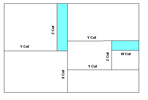
d) Cutting Complexity: Here you can specify the required type of cut.
There are different options available in Cut Complexity they are
For the first three options the Allow trim Cuts (Z and W) Cuts becomes Enabled.
Z-Cut: Piece Cut position is parallel to Y-axis but width of piece is less than strip width.
W-Cut: Piece Cut position is parallel to X-axis but width of piece is less than strip width.
The different types of cut are shown in fig. below
e) Slider Movement: Slider can control the quality of results that you want. Quicker results will give results faster (not optimized). As the slider moves from left to right the quality of results improves (results are optimized but at the expense of time)
f) Minimum Breakout Distance: This allows the user to set the minimum breakout distance required for easy breakout.
This page contain Two Button namely Optimize and Re Nest.
After Inputting the Stocks and Parts, which are to be Nested, Press this Optimize Button, the Package will generate Required Layouts.
On Click of Re Nest button will nest the remaining Parts in the remaining Stocks.
This Button will be active only if there are some non-confirmed layouts in the Solution.
After normal optimize if user does not like some layouts, then he can reject those layouts in summary page. Then on click of the Re Nest Button will nest the remaining Parts in the remaining Stocks.
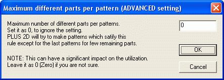
g) Maximum Different parts in Pattern :This option is used for no. of different parts you want to set in a pattern or Layout. When you click on this option, a dialog box pops up, as shown below. Give the desired value, in the edit box, so that you will get pattern with required no. of parts. To ignore the setting put zero in the edit box as shown below.
Save Setting : This option is used to save settings. Eg. If you are using different machines to cut parts. Then add values in setting page, click on 'Save Setting'. A dialog will appear, add name it for current setting and click on OK button. You can save kerf, Offcuts information, Cutting Complexity, Minimum breakout distance and no. of parts in pattern.
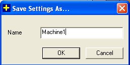
Save Settings Dialog
Load Setting : This option is used to load setting. Click on Load setting button then a dialog will appear as shown below. Select required settings and then Click on Load button.
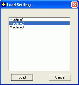
Load Settings Dialog